A Beginner’s Guide to Progressive Cavity Pump Diagrams
Progressive cavity pumps are widely used in various industries for their efficiency in handling viscous fluids. Understanding the diagrams associated with these pumps is crucial for anyone involved in their operation or maintenance. This guide will walk you through the fundamental aspects of progressive cavity pump diagrams, including their components, working principles, and applications.
What is a Progressive Cavity Pump?
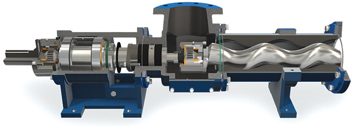
A progressive cavity pump, also known as a screw pump, is a type of positive displacement pump. It consists of a helical rotor that rotates inside a stator, creating cavities that move fluid from the inlet to the outlet. This design allows for smooth and continuous flow, making it ideal for transferring thick, corrosive, or shear-sensitive fluids.
Key Components of a Progressive Cavity Pump Diagram
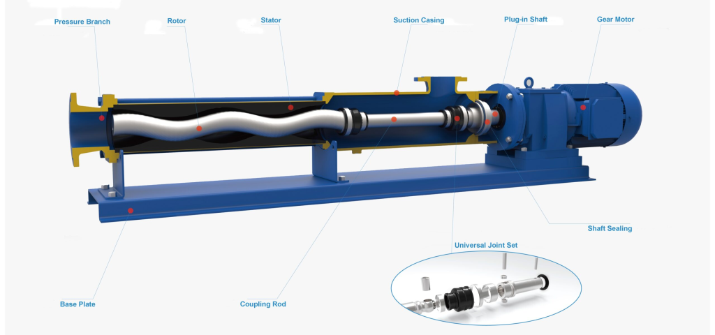
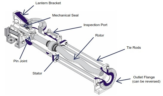
Understanding the components of a progressive cavity pump is essential for interpreting its diagrams. Here are the key parts typically illustrated:
- Rotor: The helical component that rotates and moves the fluid through the pump.
- Stator: The stationary part that surrounds the rotor, creating the cavities for fluid movement.
- Inlet: The entry point for the fluid to enter the pump.
- Outlet: The exit point where the fluid is discharged from the pump.
- Drive Shaft: The component that connects the rotor to the motor, allowing it to rotate.
- Bearing Housing: Protects the bearings that support the rotor and ensure smooth operation.
- Discharge Pressure Gauge: Monitors the pressure of the fluid exiting the pump.
Understanding the Diagram
Progressive cavity pump diagrams typically represent these components in a simplified manner, allowing for easy identification and understanding. Here’s how to read a typical diagram:
- Flow Direction: Arrows often indicate the direction of fluid flow, from the inlet to the outlet.
- Labels: Each component is labeled clearly, making it easier to reference during discussions or troubleshooting.
- Color Coding: Different colors may be used to represent various parts or to highlight specific functions, such as electrical connections or fluid paths.
Working Principle of a Progressive Cavity Pump
The operation of a progressive cavity pump can be broken down into several key stages:
- Fluid Entry: The fluid enters through the inlet as the rotor turns.
- Cavity Formation: As the rotor rotates, it creates expanding cavities between the rotor and stator.
- Fluid Transport: The rotation of the rotor moves the fluid through these cavities toward the outlet.
- Fluid Discharge: Once the fluid reaches the outlet, it is expelled at a consistent flow rate.
This continuous flow mechanism is what makes progressive cavity pumps particularly suitable for handling viscous fluids that would be difficult to pump using other types of pumps.
Applications of Progressive Cavity Pumps
Progressive cavity pumps are versatile and find applications in various industries. Some common uses include:
- Wastewater Treatment: Transporting sludge and other viscous waste materials.
- Food and Beverage: Handling food products, including sauces, pastes, and other thick liquids.
- Chemical Processing: Pumping corrosive or abrasive chemicals safely.
- Oil and Gas: Transferring crude oil or drilling fluids in extraction processes.
Advantages of Using Progressive Cavity Pumps
There are several advantages to using progressive cavity pumps, particularly in applications involving challenging fluids:
- Smooth Flow: The design allows for a continuous, non-pulsating flow, reducing system stress.
- Versatility: They can handle a wide range of viscosities and fluid types.
- Self-Priming: Progressive cavity pumps are capable of self-priming, making them suitable for various installation scenarios.
- Low Shear: The gentle pumping action minimizes the risk of damaging sensitive materials.
Conclusion
Understanding progressive cavity pump diagrams is essential for anyone involved in the operation, maintenance, or design of these pumps. By familiarizing yourself with the key components, working principles, and applications, you can enhance your knowledge and skills in managing these effective fluid transfer devices. Whether you are in the field of wastewater treatment, food processing, or chemical manufacturing, mastering these diagrams will empower you to make informed decisions and optimize pump performance.